What is HDI PCB?

HDI PCB is the abbreviation of high density interconnector PCB. HDI PCB manufacturer makes the HDI board by increased layers through micro-blind&buried vias.

HDI PCB board is a compact product specially designed for small capacity users.

The HDI board includes the following via types:

Microvia PCB: Na indústria de PCB, vias com diâmetro inferior a 150um (6mil) são chamadas de microvias.

Vias enterradas: As vias ficam enterradas na camada interna, geralmente não visíveis no produto acabado. 

Blind vias: The blind vias are drills from top layer or bottom layer to a certain inner layer. They are not through the whole HDI board. 

Characteristics of HDI PCB Board

Menor e mais leve

HDI PCB manufacturer make the HDI PCB board through continuous lamination and laser drilling with a large number of micro-buried blind holes. So it has the advantages of being light, thin, short, and small.

Alta densidade

High density interconnect PCB design with more vias, traces, copper pads and inner layers. The via diameter is usually less than 150um, the line width and line spacing do not exceed 76.2um, also the thickness of the interlayer dielectric is less than 80um.

Melhor desempenho elétrico

HDI PCB boards have better electrical performance due to multiple pressing and plating. In addition, the HDI PCB board has better improvement for radio frequency interference, electromagnetic wave interference, electrostatic discharge, heat conduction, etc.

Altos requisitos para plug vias

At present, HDI PCB board buried& blind vias plugging technology is painful for HDI PCB manufacturer. Quality problems will involve vias cavity,uneven dielectric thickness and uneven board edge if HDI PCB manufacturer does not do well with buried and blind vias.

Features of HDI PCB Board Manufacturing

The HDI PCB manufacturing process is usually different from that of other standard PCBs, The following are some special characteristics of HDI PCB board manufacturing.

Múltiplas Laminações

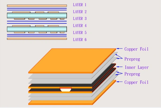
Lamination of PCB core board, PP and copper foil. Unlike other standards PCBs, HDI PCB boards go through the lamination process multiple times. These continuous laminate structures help prevent movement and breakage during drilling.

Através da tecnologia in pad

HDI PCB with via in pad technology is that the via be drilled in copper pad and filled with resin or copper materials. Then plating a layer copper to cover the via, so the pad can be used in soldering.

Tipos de vias de preenchimento

Via filling type should generally be determined based on specific application and PCB requirements. Filling materials used include chemical plating, silver filling, copper filling, conductive resin, and non-conductive resin. The most common via filling material is a non-conductive resin.

Tecnologia de perfuração a laser

Laser drilling is widely used in HDI PCB design. The laser heads can produce laser light up to 20 microns in diameter. It’s easy to cut metal and fiberglass and produce very small and clean vias. Using smooth glass fibers with a lower dielectric constant allows for smaller vias.
Capacidades de fabricação

Item Parâmetros técnicos    Especificação
Largura/espaço mínimo da linha do circuito 2,7/2,7 mil Espessura de cobre acabada H oz
Anel mínimo de almofada PCB da Via  3 milhões  Distância entre a borda do furo e a periferia do anel 
 Anel mínimo de almofada PCB de PTH 5 milhões  Distância entre a borda do furo e a periferia do anel  
 PCB mínimo por tamanho 3 milhões  Espessura da placa < 1,2 mm 
 Espessura mínima do PCB de 4 camadas 0,4 mm  Espessura Final da Placa
Espessura mínima do PCB de multicamadas 0,4 mm Espessura Final da Placa
Espessura máxima do PCB  3,2 mm  Espessura Final da Placa 
 Dimensão máxima do PCB 609×450 milímetros  PCB de face única e dupla
 Espaço entre a linha e a borda da placa 10 milhões  Fresagem de Contorno 
 Máximo de camadas de PCB 40 camadas   
Cor da máscara de solda PCB Verde, preto, azul, vermelho, branco, amarelo,  
Cor da serigrafia PCB Branco, preto, amarelo  
Acabamento de superfície PCB HASL,ENIG,ENEPIG,ImAg,ImTin,OSP, chapeamento de ouro duro  
Espessura máxima de cobre de acabamento 2 onças  
Espessura dielétrica 2,5 milhões  
Material PCB FR-4, substrato de alumínio, Rogers4350C, poliimida  
Tecnologia Especial Orifício escareado, via in Pad PCB, PCB cego e enterrado  

Tipos de PCB HDI


Empilhamento 1+N+1

Existe apenas uma broca cega e enterrada que conecta diretamente duas camadas adjacentes. Por exemplo, a camada 1 e a camada 2 estão conectadas ou a camada X está conectada à camada (X-1).

Empilhamento 2+N+2

O furo cego da camada externa do furo de passagem para a terceira camada pode ser conectado diretamente à camada 1-3, ou pode ser conectado à camada 1-2 e à camada 2-3 separadamente.

Qualquer camada

Existem conexões de microvias entre quaisquer camadas adjacentes. Por exemplo, L1-L2,L2-L3,L3-L4,L4-L5,L5-L6,L6-L7,L7-L8… etc.

Processo de fabricação de PCB HDI

Camada interna

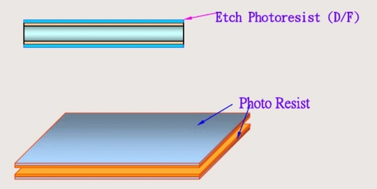
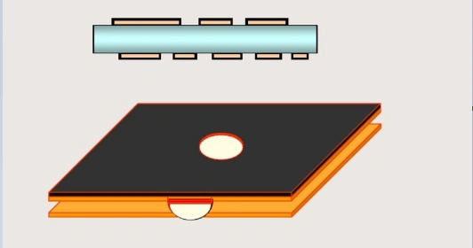
The first step is cut material sheet into working panel, then start to make Inner Layer that uses dry film to transfer PCB pattern to the copper clad by exposure and development processes.

King Sun PCB’s inner layer production capability is presently 3mil line/3mil space for Hoz and 1oz copper.

Revestimento de óxido preto

Black oxide makes core to have a uniform fluff layer that increases the bond strength between the copper foil and prepregs. It also removes grease and burs from the material surface to ensure cleanliness before lamination.

Laminação de camada interna

This lamination is made for blind vias and buried vias layers. The first step is stack and fix the prepreg sheet and the oxidized inner layer board in position. Then laminated the copper foils, prepregs and inner layer through automatic pressing machine. 

Some HDI PCBs are multiple laminations for different PCB blind&buried vias designs.

Empilhamento 1+N+1: Este tipo de PCB HDI é laminação única.

Empilhamento 2+N+2: Este tipo de PCB HDI tem duas laminações.

Stackup Anylayer: This HDI PCB type is multiple laminations.

Perfuração da camada interna (vias cegas e enterradas)

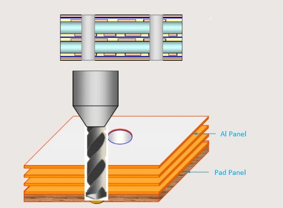
After first lamination, then blind vias and buried vias will be drilled.

When the via diameter is more than 0.2mm, we will use traditional CNC drilling machine.When the via diameter is less than 0.2mml, we will use laser drilling.

Revestimento da camada interna

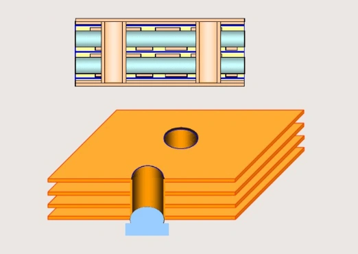
After blind vias and buried vias be drilled, the vias need to be plated before outer layer lamination. Board thickness and via diameter aspect ratio is not more than 10 to ensure the via wall plating is good.

Laminação da camada externa

The next PCB manufacturing processes are as same as standard multilayer PCB.

A aplicação do HDI PCB

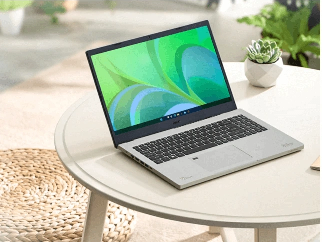
  • Mobile communication devices and notebook computers. Moreholes, light weight, small size, strong function.
  • Computer and network communication equipment and large equipment. Few holes, high layer acounts, impedance control for transmitted signal trace.
  • Portadores de chips para embalagens LSI, incluindo pads e flip chips, etc. Largura e espaçamento de linha pequenos (geralmente menos de 2 mils), alta precisão, abertura pequena (1-2 mils), espaçamento de abertura pequeno (≤5 mils), bom calor resistência e pequeno coeficiente de expansão térmica do substrato.

Porque escolher-nos?

Fabricação de PCB de giro rápido

Podemos fazer protótipos de PCB com um prazo de entrega muito rápido:

Contagem de camadas Prazo de entrega padrão Volta rápida
1-2 camadas 4-5 DIA 24 horas
4 camadas 5-6 DIA 48 horas
 6 camadas 7-8 DIA 96 horas
 8 camadas 9-10 DIA 140 horas
 10 camadas 10-12 DIA 192 horas
 
Tecnologias complexas de PCB

Fazemos PCBs muito complexos e especiais como abaixo:

  • Via no Pad PCB
  • PCB de moeda de cobre incorporada
  • PCB de retroperfuração
  • PCB de slot de profundidade
  • PCB de furo escareado
  • PCB de vias cegas e enterradas