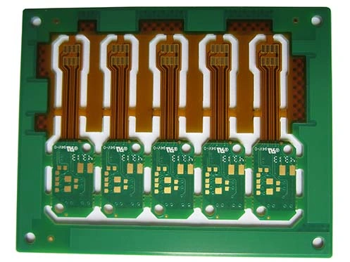
Rigid Flex PCB Technology
What is Rigid-Flex PCB?
Flex Printed circuits and rigid printed circuit boards gave birth to a new product, Rigid Flex PCB.
This printed circuit board contains one or more rigid areas and one or more flexible areas.
They are formed by pressing and other processes and have circuit boards with FPC characteristics and rigid PCB characteristics.
Advantages of Rigid Flex PCB
- Lighter
- Dielectric is thin
- Transmission routing is short.
- Small through hole
- Small noise signal, high reliability
- Flexible to change shape in special space requirements
- Resist high and low temperatures and fire.
- It can fold and doesn’t affect the transmission.
- Against electrostatic disturbance
Rigid Flex Circuit Boards Weakness
- The fabricate technology is complex: it involves rigid PCB and Flex PCB technology; it’s very complex to make them at the same time.
- The cost of equipment is expensive for both rigid PCB and flex PCB.
- If one board is damaged, another boar is unuseful.
Application
Rigid Flex PCB is widely used in medical equipment, smartphones, drones, intelligent wearable equipment, robots, curved displays, high-end industrial control equipment, aerospace, aviation satellites, and other fields.
Flexible Rigid PCB will able to shine in the near future with its excellent physical characteristics following the development of intelligent equipment to high integration, lightweight, miniaturization, and the new requirements of industrial 4 for personalized production.
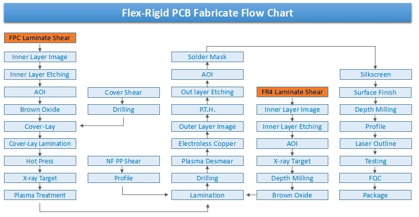
Rigid Flex PCB Manufacturing Process
1. Material Selection
The DuPont copper clad material flexible plate (AP adhesive series) flexible polyimide substrate. Polyimide has very good flexibility and excellent electrical and thermal properties, but it is hygroscopic and larger, not alkali-resistant.
For rigid plates, the rigid material of the PI resin series can be pressed together with P95 base material, and the warping deformation of the composite resin system can be avoided when the rigid flexible plate is pressed together.
For the adhesive between the deflection plate and the hard plate, it is best to use the No flow (low flow) Prepreg for pressing because its small mobility of soft and hard plastic transition regions is of great help and will not cause the transition zone to be reprocessed or cause the function of affected due to overflow.
The outer protective material pattern also is the solder layer. There are three kinds of choices. The first is the traditional film (Coverlay), which is a selection of polyimide material plus adhesive directly with the circuit board etching after protection to laminated pressed, the covering film for pressing pre forming a welding part, therefore, can not meet the assembly of more detailed requirements.
The second kind of photosensitive dry film developing type cover, with film machine after pressing, the leakage of sensitive developing welding part, to solve the problem of fine assembly.
The third category is the liquid screen printing type covering material commonly used are thermosetting polyimide materials, such as the sun and the PSR-4000 type flexible circuit board for developing photosensitive solder resist ink, this kind of material can satisfy the flexible plate of fine pitch and high density assembly requirements.
2. Key Control of the Production Process
The development flex board is based on the flexible plate and high-density multilayer rigid plate and has the same place in the process of manufacturing rigid-flex circuit boards.
However, due to the material and its particularity in the structure and application of the decision, It makes it from the design requirements, and the process is different from that of the rigid plate and flexible ordinary board.
We test and adjust to almost every aspect of production, and ultimately optimize the whole process and parameters.
3. Internal Monolithic Graphics Transfer
Pattern transfer occupies a very important position in the printed circuit board with high density, fine lines, and flexible lines.
Because the flexible single chip is thin and soft, it brings great difficulties to the surface treatment, and the cleaning condition and roughness of the copper foil surface directly affect the adhesion of the dry film and the manufacture of fine lines.
The mechanical cleaning plate has high requirements for equipment and is not suitable for pressure, which may cause substrate deformation, folding, and telescopic size; the operation is not easy to control, so we can choose to use the electrolytic cleaning method.
This method can not only ensure surface cleanness but also use the micro etching method to ensure the roughness of the copper surface, which is beneficial to the fabrication of 0.1mm~0.15mm line width/spacing graphics.
In addition to paying attention to the control of acid etching the etch rate to ensure that the design requirements of the width and spacing are, more attention should be paid to preventing the single curl, fold, is the best guide plate and auxiliary and close the exhaust system on the device.
4. Layered Positioning of Flexible Material
Poor dimensional stability and flexible substrate materials this is because the polyimide material moisture absorption is strong after wet processing or shrinkage in different temperatures and humidity in the environment of severe deformation caused by the difficulties of multilayer laminated alignment.
In order to overcome the difficulties, we can adopt the following measures: to be considered in the design of design and drawing of the spot target alignment spots to guarantee the punching hole or the rivet hole alignment accuracy, without deviation caused by interlayer graphics in the pack the lead scrap.
The positioning hole after punching by OPE can eliminate the error caused by material stretching and deformation during wet treatment. After lamination, drill holes with an X-ray to determine the offset and make drilling more accurate.
In view of the material characteristics and environmental characteristics of polyimide, draw the outer film with reference to the offset of the drilling hole so as to improve the degree of coincidence between the outer plate and the drilling plate. In this way, we can satisfy the requirement of inter-layer alignment to guarantee the 0.1mm~0.15mm ring width and guarantee the accuracy of outer pattern transfer.
5. Laminate
Even punching location by OPE, before the treatment of laminated monolithic interlayer contraposition, also has a great impact.
First, because the polyimide material is not alkali resistant, swelling in alkali solution, so in the process of treatment of black, brown, strong alkaline processes such as oil, black, brown, and other appropriate to reduce the temperature and reduce the time.
The method is feasible because the adhesive layer is used without considering the change of the bonding layer in the alkali solution.
Secondly, monolithic baking after oxidation should be avoided vertically, and the horizontal baking method should be adopted to reduce the bending deformation and keep it as smooth as possible. After baking as far as possible, shorten the molding time and moisture absorption and prevent the single again.
Because the flexible monolithic laminate before deformation, poor planeness, coupled with the adhesive sheet of the resin flow is much lower than that of the prepreg, laminated with rigid plate so as to make the adhesive sheet and a good combination and embedding fine line spacing, we chose to use the cover form a good material as laminated gasket materials, such as polypropylene film, polytetrafluoroethylene (PTFE), silicon rubber sheet, can improve the quality of laminated flexible plate.
After the test, it is considered that the ideal gasket material is silicone rubber, which can ensure the shape of the gasket and reduce the shrinkage deformation of the pressing part.
6. Drilling
The structure of rigid-flex circuit boards is complex, so it is very important to determine the optimum technological parameters of drilling a hole to obtain a good hole wall.
In order to prevent the inner ring of copper and the nail head of the flexible base material, we should choose the sharp bit first.
If the number of processed, printed boards is large or the number of holes in the processing plate is large, the drill bit must be changed after drilling a certain number of holes. Bit speed and feed are the most important process parameters.
When the feed is too slow, the temperature rises sharply, causing a lot of drilling.
The feed is too fast, it is easy to break the drill bit, bond sheet, as well as the dielectric layer of the tear and nail head phenomenon.
7. Clean Dirt and Pitting
The fouling of Flex Rigid Board is mainly composed of polyimide resin, epoxy glass fiber, and epoxy resin.
Inert flexible polyimide resin is used for a concentrated sulfuric acid solution, and the potassium permanganate solution in alkaline will produce swelling, so the conventional wet stain is very difficult.
We also tried using concentrated sulfuric acid or alkaline solution to Potassium Permanganate contamination, changing the concentration, temperature, processing time, and other parameters. Several tests did not receive satisfactory results, so we gave up the traditional wet chemical stain, using the plasma method.
8. Electroless Copper Plating and Copper Plating
It should be pointed out that the ductility of the copper plating layer is higher than that of rigid-flex bonding and flexible multilayer printed board and has higher tensile strength.
When heating shock, the total expansion rate of rigid flexible composite printed board substrate is 1.65% larger than that of the copper layer in a hole, and this index is only 0.03% in rigid multilayer plate.
Thus, it can be seen that the tensile stress of the metal hole in the rigid-flex board is much larger than that of the rigid multilayer plate. At the same time, the thickness of the copper plating layer also has a certain influence on the reliability of rigid-flex PCB.
Most rigid and flexible laminates increase the reliability of the metalized hole by increasing the thickness of the copper layer on the hole wall.
9. Surface Resist Welding and Solderability Protection Layer
Due to the flexible plate with flexural requirements during use, generally in the flexible window or flexible part, polyimide protective film protective circuit crimping is mostly used.
However, for the precision line in polyimide cladding type window, it is difficult to meet the requirements. It can use the solder mask ink coating. Solder resist ink is ordinary brittle, flexible, and can not meet the requirements. So we can choose a flexible screen printing type developing liquid photosensitive solder resist ink; both can play a solder mask, are moisture-proof, also have anti-pollution, resistance to mechanical deflection, and so on.
In addition to a method that is attached to developing flexible cover dry film, the high price of raw materials and vacuum film machine to finish well coated.
10. Outline Cutting Processing
The flex-rigid board should be milled on the milling machine. The flexible part should be paying attention to, because the flexible part is easy to distort, and the milling shape is uneven and rough.
A pad with a thickness equal to the thickness of the rigid outer layer can be inserted up, and down the flexible window, and when the milling shape is pressed, the smooth and uniform contour edge can be ensured.
If you are using a pre-open flexible window and finally using a laser to remove a waste flexible window, then a milled flexible parts shape will be ideal, but not every kind of stack can use laser mode.