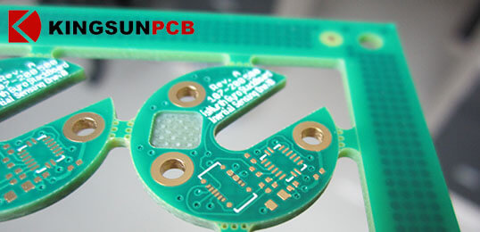
PCB Depth Slot Technology
PCB Depth control slot technology is the stepstair or groove shaped by partial routing in printed circuit boards(PCBs) manufaturing.
It has great advantages in PCB assembly as the special shape of depth routing.
- Using the depth slot of PCB edge makes card slot favor for PCB fixed and installation.
- It can avoid cold soldering as siphonic effect uses an NPTH depth slot.
- Use the depth slot in middle of PCB applied in special module application,and degrade the height of PCB assembly, achieving refinement and miniaturization.
- Use special size NPTH depth slot as resonant cavity of microwave signal, degrade signal loss and other special function.
There are two main methods of manufacture depth slot .
- Depth control routing:

The study for Capability
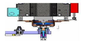
Mechanical milling:
For the depth slot PCB of mechanical milling, the precision can be +/-4mil is very high as an equipment factor.
As the depth slot is always in the depth of 0.2-0.4mm at some layers, it’s impossible to keep milling to a particular layer, there is depth tolerance as the control principle and mechanical precision. At present, main use two ways to control the depth of milling in stepstair milling process.
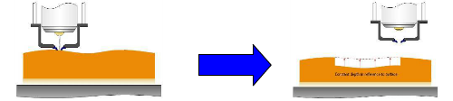
- Optical rule control Z axis height: through Optical rule induce and control Z axis height to finish depth control routing.
- Through milling tool and copper layer form a closed loop path to measure and control the height of principal axis down to finish depth control routing process. The copper layer can be surface layer or particular layer. The precision of this method can be achieved to +/-15um, so the copper thickness of stepstair minimum is 30um, it risk copper remaining at bottom layer after depth milling process.
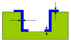
For this kind of stepstair milling PCB, all use FR4 materials and CORE+CORE to lamination. The prepreg thickness 20mil, the chip thickness 20mil. There are different size of stepstair, minimum 20x20mm,maximum 200x200mm, the depth milling is 1.0mm.
Conclusion and application prospect:
The control points and manufacturing methods of three main processes are determined through the research on the manufacturing process of the stepped plate:
(1) Mechanically controlled depth milling board to make stepped groove circuit board mainly controls the depth accuracy of Z-axis. In order to ensure depth accuracy, it is very necessary to perform compensation adjustment of milling pad and first board. The depth accuracy can reach soil 3mil.
(2) Filling the gasket press plate to make the stepped groove, the selection of gasket size and thickness is very important to the control of the amount of flow glue. At the same time, the appropriate lamination typesetting method can ensure the stable and controllable warpage and glue flow. By this method, all ordinary FR-4P sheet pressing plates can be used.
(3) The size and thickness of the gasket are the key factors that affect the control of the flow of glue. At the same time, the selection of the gasket material is the key factor for the production of different types of stepped plates. At present, different sizes can be used. Gasket material (silicone sheet and PTFE gasket), this method can be pressed by one-time pressing, and all ordinary ER-4P sheet pressing can be used by batch method.
(4) The ladder board has become a special type of circuit board due to its special application in device installation, special module design, and realization of special material functions. Its application range is constantly expanding and developing. The ladder board has become a kind of circuit board design structure favored by electronic designers, and the research on the production technology and process method of the ladder board has become a key direction for circuit board manufacturers to improve their technological level and the commanding heights of ancient technology.
References: Joseph Fjelstad, Kevin Grundy and Gary Yasumura (Next Generation Copper Based PCB Interconnection Technologies)